This article describes my experience with constructing, analysing and tuning an HF dipole antenna for the 40 meter and 20 meter bands. It should be noted, that I am not an expert in the subject, but I believe that my experiences could be useful to other newcomers, since the results are quite convincing.
The analysing and tuning section could perhaps be interesting for even experienced radio amateurs, that often tune their antennas with hardware SWR-meters and for whom a Software Defined Radio is unknown land. I know a few.
|
|
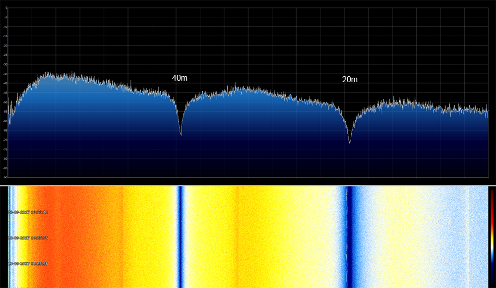
| fig.1 Spectrum of the tuned antenna. Much more about that later... |
Hardware used
Software used
Dipole antenna
Balun
Mast
Analysing & tuning
Antenna in action
Product links
Credits
Final words
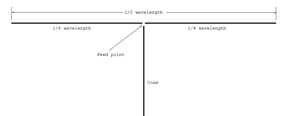
The dipole is a simple antenna, consisting of two equally long leads, with the feed point in the middle. The total length of the two leads, should be approximately half the wavelength of the frequency of interest. So as a starting point, a 40m dipole should be 20 meters (2 x 10m) long and a 20m dipole 10 meters (2 x 5m) long.
|
| fig.2 Dipole antenna basics |
You could solder the coaxial cable directly to the feed point of the dipole, with the inner core going to one side and the shield going to the other. It would work to some extent, but it is not an ideal situation, since the coax is unbalanced and the dipole is a balanced construction. With a direct coupling, the coax becomes an active part of the antenna. It will be harder to tune the antenna correctly and it would result in increased noise when receiving and ineffective transmission, if you do that as well. So that's why I would recommend a balun, which is a matching device.
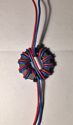
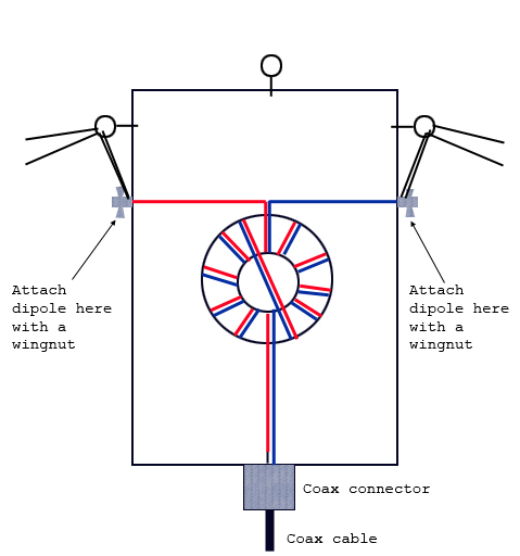
The word "balun" is short for balanced-unbalanced, and it is a simple construction that couples an unbalanced component to a balanced one. There are different types of baluns depending on the situation. In this situation a socalled "1:1 current balun" is what we need. Here's the one I have made for this project.
|
|
|
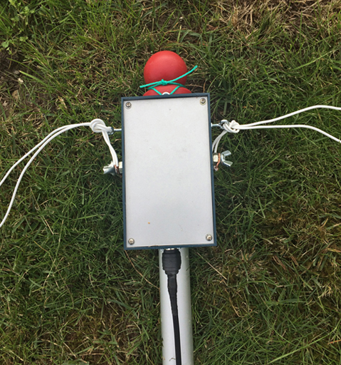
| fig.3 1:1 current balun | fig.4 The balun in a box with dipoles attached | fig.5 Inside the box |
The toroid used is a Fair-Rite FT240-31. The important figure here is '31', which refers to the mix of the iron powder used in molding the toroid. The Mix31 is ideal for HF-frequencies (acc. to The ARRL Antenna Book). I have bought mine on eBay for 11 pounds.
The wire used for the balun is 2.5 mm2. For reception only, you could use thinner wire, but for transmission a gauge like this is recommended, since the current here at the feed point is rather high. I have seen people using coaxial cable for the balun windings. I suppose that would be fine, as long as you choose a type that's flexible and that can handle the power, if the antenna is used for transmission.
I found an appropriate enclosure for the balun in my junk yard. It's just a simple unshielded plastic box. I have drilled some holes in the bottom for draining and ventilation.
As you notice, there are actually two dipoles connected to the same balun, which of course are the 40m and the 20m. Dipoles for other HF bands, eg. 80m, could be connected as well without problems (If you've got the space for it. Remember that a dipole is half a wavelength wide, so for the 80m band that is approx. 40 meters).
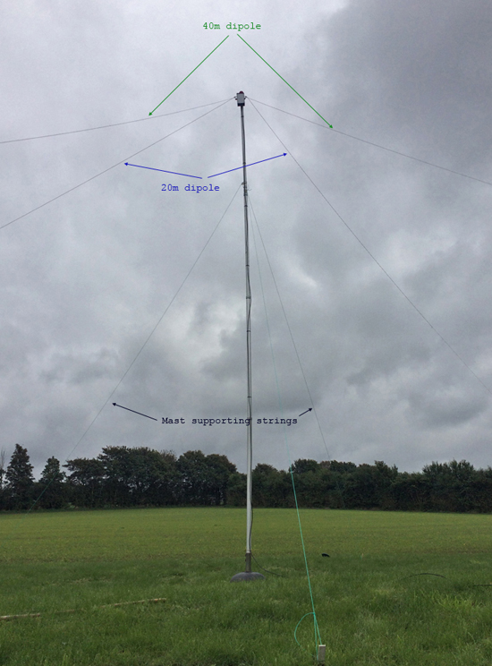
The mast is a mobile 6 meter telescopic aluminium flag pole I was given as a present years ago. It has never served as a flag pole (sorry for that, whoever gave it to me...!) But it's perfect for this project.
|
|
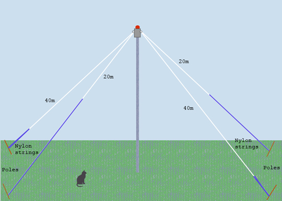
| fig.6 The erected mast | fig.7 Sketch of the arrangement |
As you notice, the dipole legs are bending down towards the ground, forming what is called an "Inverted V" or "Inverted Vee". The benefit of that arrangement obviously is that you - in this case - won't need a lot of 6 meter flag poles to keep your dipoles horisontal. The cost is, that your dipoles become slightly less efficient, because some of the energy in the dipole legs will go to ground more easily. Where there's a benefit, there will often be a cost. However an inverted V is less directional compared to a straight horisontal dipole, i.e. more equally sensitive in all directions.
The angle of the '∧' should be > 90o
OK, we have now built a new antenna and we have done everything right, according to all the knowledge we have. But does it really perform the way we expected? We wouldn't know for sure, unless we make an analysis.
A hardware antenna analyser, that provides you with a detailed visual spectrum of the antenna's characteristics, is very expensive. So for most non professionals, that's not an option.
Fortunately, with the launch of the Software Defined Radio and some inexpensive hardware components, it is actually possible to achieve something similar. It's probably not good enough for the professional, but for the amateur, it's a very useful tool.
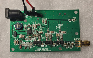
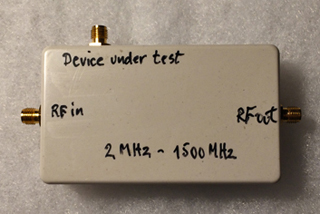
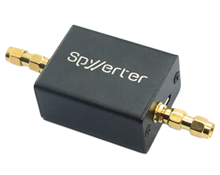
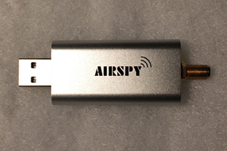
Let's start with the hardware. I use a Noise Source, an SWR-bridge, a SpyVerterR2 upconverter and an AirSpy Mini SDR. For my part, I only had to buy the SWR-Bridge and the Noise Source, since I already have the SpyVerterR2 and the AirSpy Mini for receiving HF radio.
|
|
|
|
| fig.8 Noise Source | fig.9 SWR-Bridge(hand writing is mine) | fig.10 SpyVerterR2 upconverter | fig.11 AirSpy Mini SDR |
|
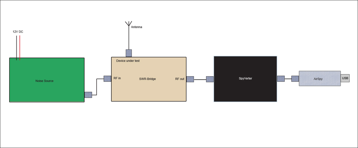
| fig.12 The hardware should be connected like this |
Note that the Noise Source comes without a 12V DC power supply. You probably have one in a drawer somewhere...
With the hardware connected, now let's turn to the analysing software "SpectrumSpy". SpectrumSpy is included in a free software package "Windows SDR Software Package", which can be downloaded here:
Windows SDR Software Package
This package also includes the excellent receiver software SDRSharp. The package is a zipped directory. All you have to do is to unzip it, and you are ready to go. No installation procedure (wish more software were like that!)
Before we launch SpectrumSpy, there's one line in the file SpectrumSpy.exe.Config we have to edit (with a plain text editor, like NotePad!):
<add key="core.useBiasTee" value="False" />
must be changed to
<add key="core.useBiasTee" value="True" />
This will send the required power to the SpyVerter.
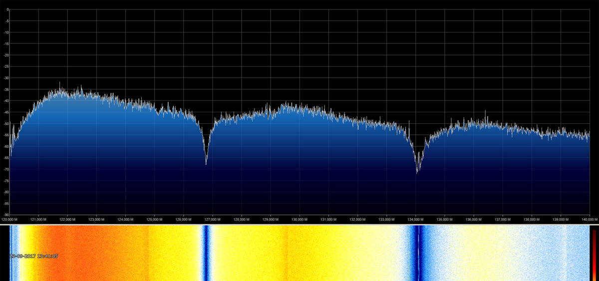
When I launced SpectrumSpy with my new HF-Dipole antenna coupled to the SWR-Bridge and the Noise Source powered up, I saw this nice spectrum:
|
| fig.13 You clearly see two significant notches or resonance points, that must be the 40m and 20m dipoles |
There's one matter here we have to deal with though. If you look at the horisontal scale (X-axis) you'll notice that the resonance points are around 127 MHz and 134 MHz. So what is going on here? That's far from 40m and 20m HF. We would have expected something like 7 MHz and 14 MHz.
Remember I mentioned that the SpyVerter is an upconverter?
Ahh, here we have the explanation. The SpyVerter shifts the frequency up by 120 MHz. So 127 MHz corresponds to 7 MHz and 134 MHz to 14 MHz. That's more like it!
SpectrumSpy is not - as opposed to SDRSharp - designed to work with the SpyVerter upconverter. But with this simple conversion in mind, it works just fine!
Perhaps I'd better explain why the SpyVerter upconverter is needed in the first place. The Airspy Mini SDR (as well as the Airspy R2 SDR) can receive from 24 MHz to 1800 MHz, which means that the HF bands are out of reach without the upconverter. A new SDR model "Airspy HF+" is on the stairs. This model covers the frequency ranges 0 Hz to 31 MHz & 60 MHz to 260 MHz, so an upconverter won't be needed here.
Now that we have a working analysing tool, it's time to fine tune the antenna to the desired frequencies. The 40m band covers the frequency range from 7.0 MHz to 7.2 MHz. Most often I listen to the upper part of the band, so I will set 7.15 MHz as the target resonance point for 40m.
The 20m band covers the frequency range from 14.0 MHz to 14.350 MHz. Also here I most often listen to the upper part of the band, so here I will set 14.2 MHz as the target resonance point. Which means that the notches - with the upconversion in mind - should be at 127.15 MHz and 134.2 MHz on the X-axis.
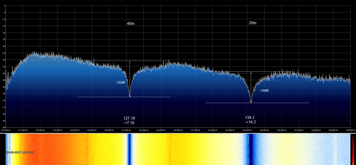
The initial spectrum shows that we are close, but not bang on. Fortunately the frequencies are too low, so all we have to do is to cut a bit of the dipole wires to make the frequency move up. I cut 5 to 10 cm a couple of times and checked the spectrum for each cut. Patience is required here. It's easy to cut off, much harder to cut on, if you know what I mean. Finally I hit the targets close enough, and here's the spectrum of the trimmed and tuned dipoles:
|
| fig.14 Tuned! |
Except from the resonance frequency, one more interesting thing you can read from the spectrum, is the efficiency of the antenna. I have drawn some help lines to illustrate the depth of the notches. For 40m that is around 25dB and for 20m it is around 24dB. The depth of the notch is the socalled "Return Loss". The deaper the better. Most radio amateurs use the unit SWR or VSWR (Standing Wave Ratio or Voltage Standing Wave Ratio). Return Loss can be converted to VSWR using a formula. But it is much easier to use this online converter (which of course is based on that formula):
Return Loss to VSWR Calculator
Using this converter I can now read the approximate SWR for my dipoles:
| 40m | 20m | |
|---|---|---|
| Return Loss | 25dB | 24dB |
| SWR | 1:1.12 | 1:1.13 |
Not so bad. Quite good actually :-)
Finally I notice from the spectrum that the 20m notch is slightly wider, meaning that this dipole must be a litte more broadbanded. I have no *explanation for that. It's exactly the same type of wire used for both.
*Update
Nice people have made me aware, that there is a relationship between bandwidth and frequency and probably also wire gauge. I will study this relationship a little closer and make a note about it, when things are clear to me - eventually :-)
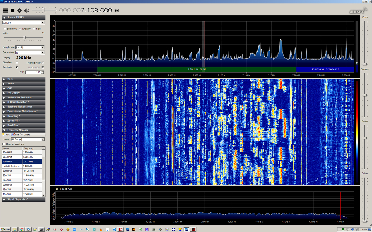
Here you see a couple of screen shots of the antenna receiving on 40m and 20m during a weekend contest. The signal goes from the antenna to the SpyVerterR2 upconverter, then to the AirSpy Mini SDR, and finally to my Windows PC via USB, where the signal is further processed and presented by the receiver software SDRSharp. The audio simply comes out of the PC speakers.
|
| fig.15 Receiving on 40m |
|
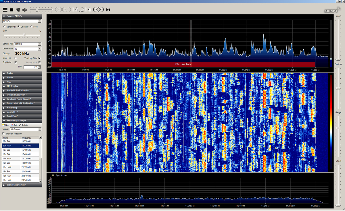
| fig.16 Receiving on 20m |
|
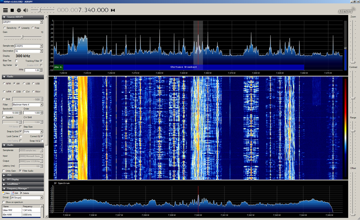
| fig.17 And if you fancy Short Wave radio listening, there are plenty of stations... |
If you are a radio amateur, you will probably think: "That looks very cool, but how do I transmit?". The type of SDR used in this project, is not capable of transmitting and the software used, does not support it either. But I'm sure it would be possible to combine this setup for receiving with a conventional transceiver for transmitting, using a relay. I have no further details on that, since I have no experience with it (yet).
| Hardware |
|---|
| Ferrite Core Toroid |
| AirSpy Mini |
| SpyVerterR2 |
| SWR-Bridge |
| Noise Source |
| Software |
| Windows SDR Software Package (It is free. Contains both SpectrumSpy and SDRSharp (SDR#) |
For the antenna construction part, much of my knowledge comes from the ARRL Antennabook and from reading numerous Internet articles. I should also mention my father in law, Thomas Møller OZ3YT, who is a very experienced radio amateur. I use to call him "The antenna doctor" :-) He has taught me a lot.
For the antenna analysing part, I have learned much from this Youtube video by Mile Kokotov from Macedonia. Recommended!
I am not in any way affiliated with the products mentioned. I just find that they are good products, giving me great value for the money I spent.
All the best and good luck,
Anders J. Ørts
Randers, Denmark
